Viewing Directional Well Profiles
View the profile of directional wells. Profile Viewer includes three main views:
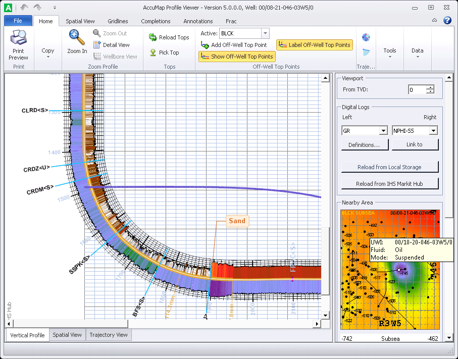
- Vertical Profile, which shows a side profile of the directional wellbore. Use this view as your primary view to configure numerous details including selecting logs to display, placing tops, configuring the map inset view, and creating completions and annotations.
- Spatial View, which shows a bird's eye view of the wellbore. Once you've configured the wellbore display using the Vertical Profile view, use the Spatial View to refine the display and to get a different perspective on the wellbore. Some of the same toolbars and toolbar options available in Vertical Profile view can also be accessed using Spatial View. Where this is not the case, the toolbar or toolbar option are grayed. Hover the cursor to display data about the underlying object in a tooltip.
- Trajectory View, which enables you to rotate the wellbore both horizontally and vertically by simply clicking and dragging your cursor anywhere on the display pane.
The profile pane shows user and system tops, user formations, and completions. Lower the top of the viewport to accentuate the horizontal run. Display digital logs on either side of the wellbore to add interpretive colors to the wellbore, or display a raster log.
To view directional well profiles
- With a DataCard for the desired well displayed, in the Home toolbar, click Profile Viewer (
 ).
).
The dialog box appears.
- Using the Viewport pane, type the desired depth at which to start the top of the viewport. Profile Viewer honors the depth you type as faithfully as it can while still rendering the log at the highest quality possible given the horizontal and vertical extents in which it can render the logs. To display the optimal rendering of the wellbore, type a TVD depth of 9999. Profile Viewer sets the top of the viewport to 1500, for example, if that results in the most faithful reproduction of the wellbore.
The map inset that appears in the Nearby Area pane to the right of the Profile Viewer wellbore display pane shows a bird's eye view of the wellbore at a given depth based on the top that is selected in the subsea drop-down list. The subject well is surrounded by surface wellheads within 5 KM on all sides.
- In the Digital Logs pane, select the logs to display in the left and right tracks of the borehole. If you have a local LAS file you would prefer to display for the well, click Link to Proprietary and then browse to that LAS file. This establishes a connection in the AccuMap configuration files so that this LAS file is loaded by default in the future.
Upon launching a well, Profile Viewer searches for logs in the following sequence: First it searches for a local LAS file (if you previously established a link for this well using Profile Viewer) with the same curves defined in the Left and Right tracks or one of their aliases. If unsuccessful above, it next searches the S&P Global Inc. Hub for the curves defined in the Left and Right tracks or one of their aliases. Finally, if unsuccessful above, Profile Viewer retrieves a raster log from the S&P Global Inc. Hub displaying the longest available MD segment in 1:240 scale by default.
If you change computers after establishing a link between a well and a local LAS file, copy the files located in the %appdata%Roaming\IHSDigitalLogs\ on the old computer to the same location on your new PC in order to maintain this link to proprietary LAS files. To toggle between an established local LAS file and digits available on the S&P Global Inc. Information Hub, click Reload from Local Storage and Reload from S&P Global Inc. Hub.
Click Definitions in the Digital Logs pane to display the dialog box, where you specify the curve aliases that are associated with various curve families in order to maximize the possibilities of locating the desired curve.
- Using the Mini Profile pane, which appears to the right of the Profile Viewer main display pane, drag the green rectangle to control the portion of the wellbore visible in the main display pane (as depicted below). The size and dimensions of the green rectangle represent the current display pane extents in relation to the wellbore. The position of the green rectangle in relation to the surrounding Mini Profile pane mirrors the relative position of the wellbore in the main display pane.
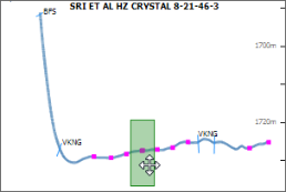
Right-click the Mini Profile pane and select Copy from the context menu to save an image of the pane to the Windows Clipboard in BMP format.
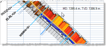
- Using the Home toolbar, click Pick Top (
 ) to display the dialog box where you locate the top to place along the wellbore, and then click OK. Your cursor is loaded with the top to place. Click to place the top at the desired measured depth along the wellbore as depicted below.
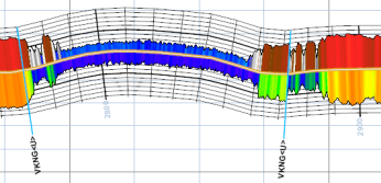
The user top is placed in the well in the User Tops database, which is used throughout AccuMap. Move an existing system <s> top to convert it to a user <u> top. The top is updated in the user tops database. System tops display <s> after the formation top name; user tops display <u>. You can place multiple instances of the same formation top in the same wellbore, for example, when a horizontal run exits and then renters the target formation, as depicted below.
To convert all instances of system tops in a wellbore to user tops, right-click a system top and from the context menu, select Convert all System Tops to User Tops.
To delete a user top, right-click the actual formation top in the wellbore, not the formation top name alongside the wellbore, and from the context menu, click Delete. Where the user formation was created by moving a system formation, the system formation reappears when the user formation is deleted. In cases where there are multiple instances of the same user formation, one of which was created by moving a system top, when the last top is deleted, the original system top appears in the default location.
Undo functionality, which appears in the top-left of Profile Viewer only applies to formation top actions (picking, moving, deleting).
- Select from the following options:
- For raster logs, the longest segment is displayed by default. Select a different segment using the MD Raster Logs Lookup Table drop-down list. The original scale of each raster log appears in both the MD Raster Logs Lookup Table, and in the left margin of Profile Viewer, however, the scale in some portions of the log may be modified slightly by the algorithm that applies deviation to the log.
Profile Viewer posts the log scale at the bottom of the raster segment after comparing the top and bottom raster log scales and selecting the one with superior information.
The profile view of the well path represents a graph of true vertical depth vs. vertical section (known as the projected horizontal displacement) onto a single plane. Profile Viewer uses vertical section values from the directional survey table. If the vertical section values in the directional survey table are missing or set to zero, the profile view may not reflect the actual well path for the deviated borehole.
- Pick formation tops that are not directly on the wellbore. These tops are referred to as Off-Well Tops, or Off-The-Wellbore Tops. Pick an off-well top to capture the subsea position of the top, even if the subject well has not penetrated the top. The example below shows the Cardium and Blackstone off-well tops. It also shows multiple instances of the user formation, U-CrSh, which corresponds to the shaley part of the Cardium formation.

To add depth points that adjust an off-well top, select the off-well top from the Active drop-down lists, which appears in the Off-Well Top Points group of the main ribbon. Click Add Off-Well Top Point (  ) and then click to place a control marker at the depth at which to move the active top. Move control markers to either a different depth or to a different horizontal location along the formation top by first clicking Show Off-Well Top Points (
 ) to display the markers and then dragging the marker to the desired vertical or horizontal location. To display the formation top name followed by the <OFF> prefix, click Label Off-Well Top Points (
 ) in the main ribbon.
For details on off-well tops, see Related Topics below.
If a desired top doesn't appear in the Active drop-down list, using the Surfaces box that appears under the Mini Profile pane, increase the number of tops shown.
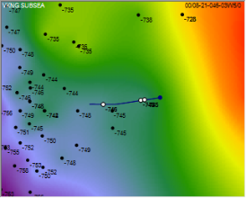
- Select the depth to display using the Subsea drop-down list in the Nearby Area pane to select one of the tops picked in the wellbore. The location of that top in the wellbore appears as a white circle along the wellbore in the Nearby Area pane as depicted below. Where the same top is picked multiple times, multiple white circles appear along the wellbore.
To further customize the Nearby Area pane, including the color scheme, wells to display, and off-well tops and depths, click the Spatial View tab in the Main ribbon.
- Using the Home tab, select from the following:
- Zoom to the desired view. Also click Detail View or Wellbore View to zoom in or out to the ideal view with a single click.
- Display well azimuth and inclination angle markers.
- Enable the Use On-The-Fly VSEC check box to calculate vertical section values using a projected horizontal displacement formula.
- Select from the following additional options:
- Using the Spatial View tab, select display options that appear in both the Spatial View tab and in the Nearby Area thumbnail pane.
- Using the Gridlines tab, specify whether various gridlines appear in the main wellbore display pane.
- Using the tab, add user-defined completion objects in the wellbore. For details, see Related Topics below.
- Using the tab, add user-defined annotation callouts in the wellbore. For details, see Related Topics below.
- Using the Frac tab, specify the graph type to display.
- Output Profile Viewer contents to either print or PDF, and then output the data from various panes as follows:
- Display Pane - click Copy Profile to copy the display pane to the Windows Clipboard in EMF format. Click Copy Current View to copy only the area within the display pane current extents to the Windows Clipboard in BMP format.
- Nearby Area - right-click the pane and select Copy as BMP or EMF from the context menu.
- Mini Profile - right-click the pane and select Copy from the context menu to save the image to the Windows Clipboard in BMP format.
- If you modify the user tops for the well displayed in the Profile Viewer dialog box, click Reload Tops (
 ) to update the tops in the profile pane.
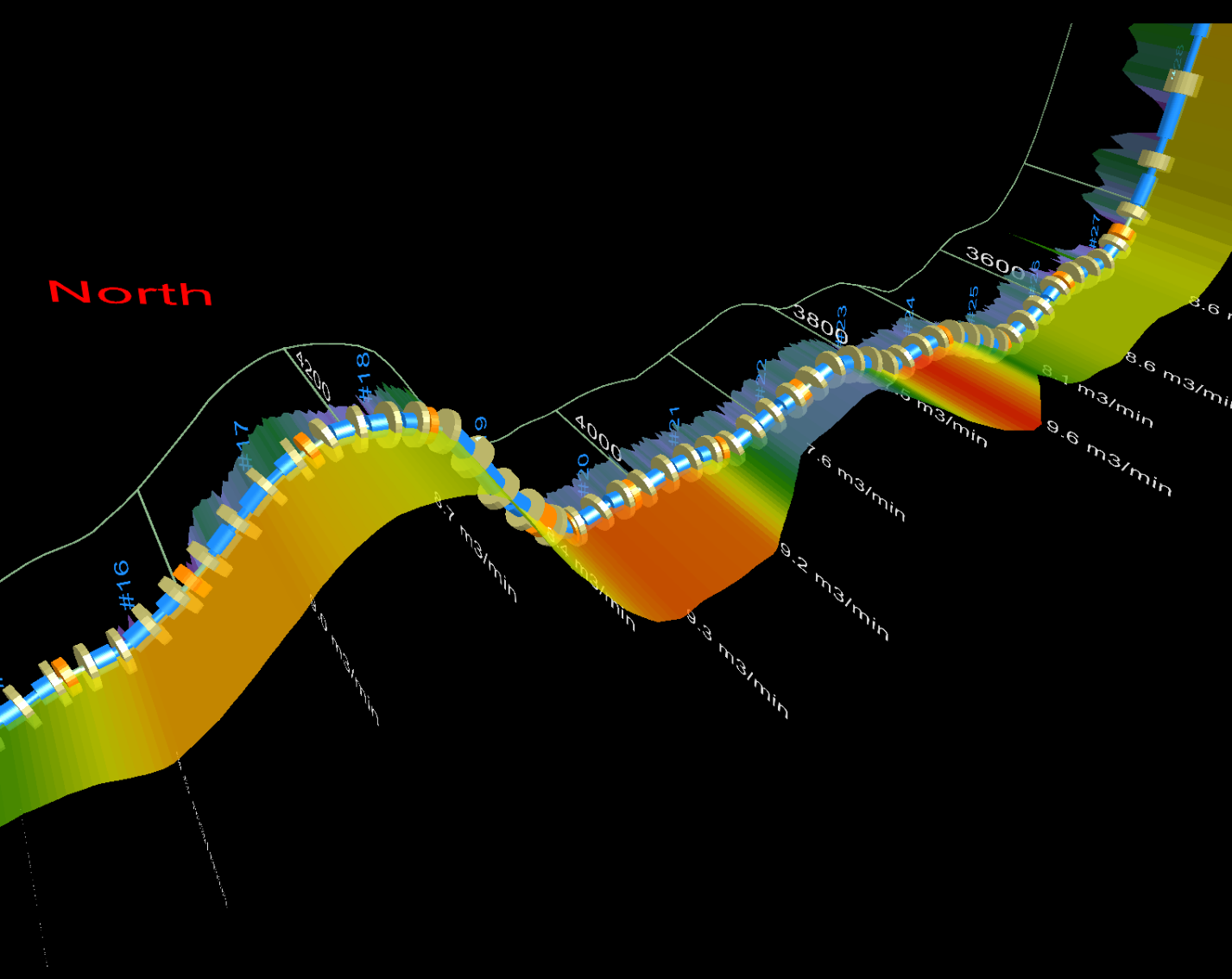
- To rotate the wellbore to focus on a specific view, click the tab in the bottom-left of the Profile Viewer dialog box and then click and drag anywhere on the display pane in order to rotate the wellbore in that direction. Roll the mouse wheel to zoom. Hover the cursor over a given element on the wellbore to display details about that element in a popup window. See Related Topics below for further details.
 .
.
 Related Topics