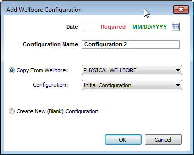
In the Wellbore editor (located within the Editors pane), you can create multiple wellbore configurations for a well. Wellbore configurations are used to calculate flowing pressures in the Production editor. Configurations are assigned a date and are used in calculations until the date of the next configuration. Temperature and deviation surveys can also be added for the initial configuration. A schematic of the wellbore is displayed on the right side of this editor.
After you have entered completion data and set temperature gradients, this data can be used in analyses and pressure calculations.
| Note: | Many rate transient analysis (RTA) analyses use sandface flowing pressures. In order to calculate sandface flowing pressures, you must enter wellbore information. |
There are two toolbars associated with the Wellbore editor: primary and schematic.
The primary toolbar has the following icons:
 Calculate Sandface Pressure — calculates sandface pressure each time you click this icon.
 Auto Calculate Sandface Pressure — automatically calculates sandface pressure while this option is enabled.
 Copy to / Paste from Clipboard — copy / paste configurations.
| Tip: | To set various elevations (for example, ground level, kelly bushing), enter these values in the Attributes tab. |
The schematic pane is located on the right-side of this editor in the Schematic pane, and has the following icon:
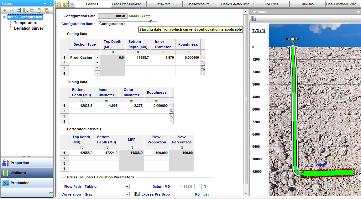
In the main pane, you can edit your wellbore profile, which is important for rate transient analysis (RTA) as it provides a model of your well to calculate sandface pressures.
Click Profile in the Editors pane; then enter values in the Casing Data, Tubing Data, Perforation Intervals, and Pressure Loss Calculation Parameters areas.
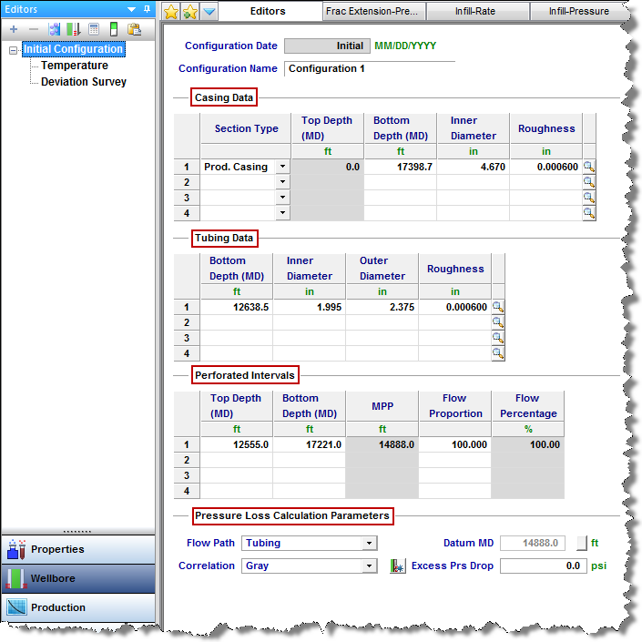
When entering casing or tubing data, clicking the ![]() icon on the right-side of each row opens the Sizes dialog box, where tubing /casing / pipe sizes can be edited.
icon on the right-side of each row opens the Sizes dialog box, where tubing /casing / pipe sizes can be edited.
If you select Pumping in the Flow Path drop-down list and Auto Template is selected (default setting), these columns are displayed in the Production editor:
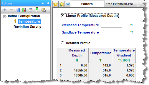
Click Temperature in the Editors pane; then enter your temperature profile.
Click Deviation Survey in the Editors pane; then enter measured depth and TVD. In this way, you can emulate a horizontal or directional well. For a vertical well, deviation data is unnecessary.
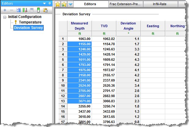
If you want to add a deviation survey with 3-dimensional data, enter your data in the Easting and Northing columns.
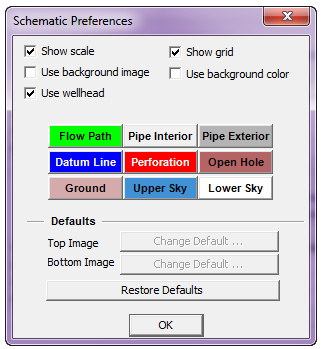
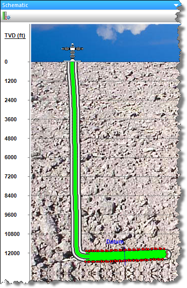
By default, the wellbore Schematic pane opens to the right of the configuration parameters. This schematic is a two-dimensional visual representation of the well information that has been provided. The depth scale appears to the left of the wellbore. The flow path of the produced fluid in the well is displayed in green, and injected fluid is displayed in red. Perforations are indicated in red, and the datum is depicted with a dashed blue line.
IHS Harmony Enterprise™ 2018.2 | Last revised: June 26, 2018
Copyright © 2018 IHS Markit Ltd. All rights reserved.