With your Harmony Optimize license, you can have analyses with gas lift and pumping flow paths. First you need to create an Optimize Configuration in the Wellbore editor. In the Pressure Loss Calculation Parameters section, update the flow path to Gas Lift - Tubular, Gas Lift - Annular, or Pumping.
Gas lift
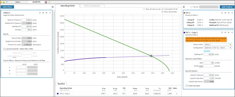
After selecting a gas lift configuration, the Outflow pane on the right-side adds a Gas Lift Injection section, which requires the following additional inputs:
- Injection Pressure
- Injection Gas Rate
- Injected Gas Gravity (this value defaults to the value entered In the Properties editor)
For information on valve depths, see show all valve curves.
Plot and operating points
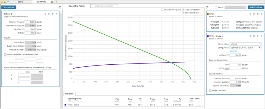
The operating points on the plot are displayed in one of the following colors:
- Green — the operating point is in the preferred range.
- Black "X" — the operating point is invalid (gas lift is not possible).
Example
In this screenshot, gas lift is not possible. This is denoted by orange highlighted text in the Outflow pane and an X icon for the operating point on the plot. Furthermore, the performance curve is displayed with a long dashed-line segment, which indicates that the producing rate is too high for gas lift to be possible.
To fix the problem, you may need to:
- change the injection pressure.
- change the injection rate.
- change the wellbore settings in the Optimize Configuration, such as the valve depth.
In this screenshot, the gas lift outflow curve is operating in the preferred range. The warning message is gone and the operating point icon is in its normal state.
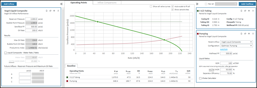
Electrical submersible pump (ESP)
Note: For ESP analysis, you must select an Optimize Configuration with the flow path set to Pumping. For more information, see Wellbore editor.
After selecting the pumping configuration, the Outflow pane on the right-side requires one additional input called Separator Efficiency.
- The separator efficiency reflects the percentage of free gas at pump conditions removed from the pump flow path (and produced up the annulus).
- GOR input is assumed to be the tubing production after gas separation.
- If over 20% of the total fluid volume is free gas at pump intake conditions, ESPs can be damaged. Calculations continue, but a warning message is displayed.
Example
In this screenshot, pumping is not possible. This is denoted by orange highlighted text in the Outflow pane and no valid operating point on the plot. Furthermore, the performance curve appears to stop at a rate of 30 bbl/d – well below an expected rate given the inflow curve for this well.
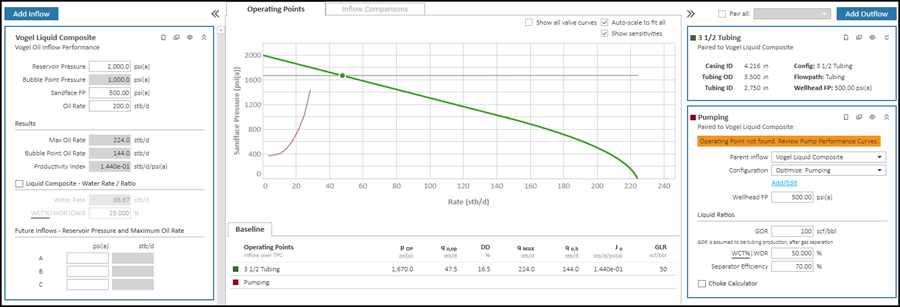
To fix the problem, you may need to:
- Check that you have correctly entered the range of rates for the pump.
- Investigate total fluid rate (oil, water, and free gas) to ensure that the pump is correctly sized.
In this screenshot, the pumping outflow curve is operating in the preferred range. The warning message is gone and the operating point icon is in its normal state.