Afterflow (Wellbore Storage) Analysis
Subtopics:
Summary of Equations for Afterflow Analysis
Summary of Equations for Afterflow Derivative Analysis
Afterflow, or wellbore storage, occurs during the initial period of a shut-in. Prior to a shut-in, the rate of fluid leaving the wellbore at the wellhead is equivalent to the rate of fluid entering the wellbore at the sandface. When the well is shut in, fluid continues to enter the wellbore at the sandface, thus compressing the fluid inside the wellbore. Pressure data is affected by afterflow, until the time comes when the rate of fluid flow at the sandface is negligible.
The purpose of analyzing afterflow data is to determine the wellbore storage constant (C), and to determine when afterflow ends and reservoir-dominated data begins. Thus, the wellbore storage constant (C) is a measure of the storage capacity associated with the wellbore volume (Vw).
Basic Definitions (Field Units)
There are two types of afterflow (wellbore storage): fluid-filled and changing liquid level.
In the fluid-filled case, the wellbore is presumed to be full of either all liquid or gas, which gets compressed as afterflow continues into the wellbore. The wellbore storage constant (C) is a function of the wellbore volume (VW) and the wellbore fluid compressibility (cwb) as shown below:
For a fluid-filled wellbore:
When both gas and liquids co-exist in the wellbore and the liquid level changes, the wellbore storage constant (C) becomes a function of the wellbore area (Awb) and liquid gradient (Gliq) as shown below.
For a changing liquid level:
or
The wellbore storage constant (C) is often converted to a dimensionless wellbore storage constant (CD) for use in analytical reservoir models.
Constant Rate Solution (Field Units)
For oil and water:
![]()
For gas:
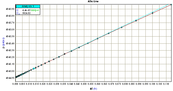
These equations are linear with respect to time and, as a result, afterflow (wellbore storage) data will form a straight line when plotted on a Cartesian plot of pressure versus delta time (p vs. Dt) as shown below.

Using the slope of this line (m), the wellbore storage constant (C) can be determined. The table below summarizes the equations used to calculate C for different fluid types and flow periods.
Summary of Equations for Afterflow Analysis (Field Units)
|
|
Flow Period |
Wellbore Storage Constant (bbl/psi) |
|
Oil |
Buildup
|
|
|
Gas |
Buildup
|
|
Derivative Analysis (Field Units)
The signature of wellbore storage on a derivative plot is a straight line with a unit slope at early time. The position of this line is used to calculate the wellbore storage constant (C). Note that wellbore storage increases as the position of this line moves to the right.
Starting with the constant rate solution (see above), the derivative with respect to the logarithm of time is:
For oil and water:
For gas:
Taking the logarithm of both sides:
For oil and water:
For gas:
This result is linear with time, and as a result, the derivative of afterflow (wellbore storage) data falls on a straight line with a slope equal to one on a log Dp versus log Dt plot as shown below.

Using any derivative point on this line, the wellbore storage constant (C) can be determined. The table below summarizes the equations used to calculate C for different fluid types and flow periods.
Summary of Equations for Afterflow Derivative Analysis (Field Units)
|
|
Flow Period |
Wellbore Storage Constant (bbl /psi) |
|
Oil |
Drawdown
|
|
|
Buildup
|
|
|
|
Gas |
Drawdown
|
|
|
Buildup
|
|