Well Locations & Boundaries
Subtopics:
Constant Pressure Boundary
A constant pressure boundary is a boundary that provides pressure support. This kind of boundary usually occurs in reservoirs with aquifer support. Steady state flow signifies that a constant pressure boundary has been reached.
Distance to Boundary
The distance to boundary is the distance between the well and the boundary. The boundary may be a no-flow or constant-pressure boundary, and may be circular or linear as shown below.
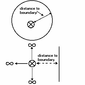
If a well is located near a single boundary, the reservoir is considered to be infinite acting in all the other directions.
Infinite Acting Reservoir
An infinite acting reservoir is a reservoir without any boundaries; therefore boundary effects will not appear on the analysis plots during the duration of the test.
No-Flow Boundary
A no-flow boundary is a boundary that does not allow flow through it. This kind of boundary usually occurs in reservoirs with sealing faults, or is created between producing wells that are equally spaced and producing at the same rate. Pseudo-steady state flow signifies that all no-flow boundaries have been reached.
Observation Well
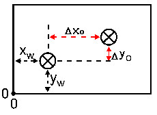
In modeling, pressure can also be calculated at a different location or observation point away from the active well. This point is known as an observation well. The location of the observation well is measured with respect to the active well location (e.g. Xw and Yw) and has the coordinates ∆Xo, ∆Yo, Zo for rectangular reservoirs or ro for cylindrical reservoirs. This coordinate system for rectangular reservoirs is shown in the diagram below.
Reservoir Dimensions
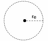
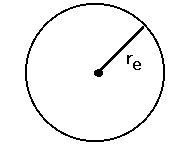
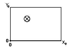
Reservoir length (Xe) is the length of the exterior reservoir boundary in the x-direction and reservoir width (Ye) is the width of the exterior reservoir boundary in the y-direction, as shown in the diagram below. Reservoir height (Ze) is the thickness of the reservoir, defined as net pay and denoted by ‘h’. (See Net Pay.)
Well Location
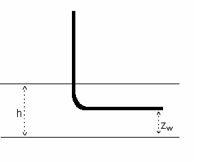
The location of the active (producing or injecting) well for rectangular- shaped reservoirs is specified using an x, y, z coordinate system, as outlined below. The distance is represented from the origin in the lower-left hand corner (Xw, Yw and Zw).
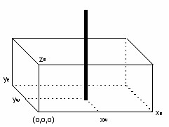
| Note: | The Zw distance is only applicable for a horizontal well and represents the distance or height from the origin (base of the formation) to the center of the horizontal leg of the wellbore. For cylindrical-shaped reservoirs, the well is always assumed to be in the center. |