Naturally fractured reservoirs have two distinct porosities, one in the matrix and one in the fractures. Although naturally fractured reservoirs consist of irregular fractures, they can be represented by equivalent homogeneous dual porosity systems (Warren and Root (1963)).
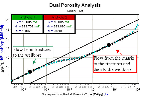
Quite often, the volume of hydrocarbon stored within the natural fractures is much lower than is stored in the matrix. In dual porosity systems, the natural fractures have much higher permeability than the matrix. When the well begins to flow, fluid travels from the high permeability natural fractures to the wellbore and is rapidly produced. Once the natural fractures have been drained, the large volume of hydrocarbons contained within the bulk of the reservoir (matrix) begins to flow. These hydrocarbons flow to nearby natural fractures and virtually all of the fluid is transported to the wellbore via these fractures.
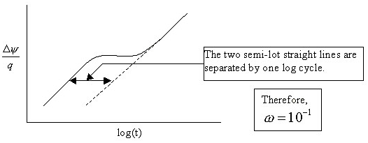
The signature of dual porosity systems on a semi-log plot is two parallel lines as shown below.
The first semi-log straight line is observed at early time and represents radial flow as the fluid, initially in the fractures, travels to the wellbore. The second semi-log straight line occurs when the fractures deliver fluid from the matrix to the wellbore. The transition period between the two semi-log straight lines occurs when fluid begins to flow from the matrix to the fractures but has not yet reached a state of equilibrium.
Be aware that dual porosity, especially the first semi-log straight line, may not be noticeable even if the reservoir is naturally fractured because wellbore storage effects could affect the data.
Naturally fractured reservoirs are characterized by the interporosity flow coefficient (λ), the storativity ratio (ω), and the type of interporosity flow.
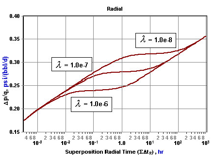
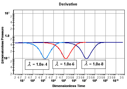
As shown in the plot below, as the interporosity flow coefficient decreases, the transition between the two semi-log straight lines is delayed. That is, the larger the fracture permeability is in comparison to that of the matrix, the more time the fractures will have to drain before the contribution from the matrix becomes significant.
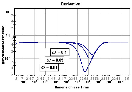
The storativity ratio (ω), essentially represents the time separation in log cycles between the two semi-log straight lines as shown below.
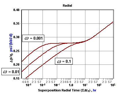
A storativity ratio of one is a single porosity system with all of the reserves inside the fractures, and a storativity ratio approaching zero is a single porosity reservoir with all the reserves inside the matrix. Therefore, as the storativity ratio is decreased, a greater portion of the reserves are contained in the matrix and the longer it takes for the matrix and fracture system to reach a state of equilibrium. This is shown in the following plot:
The signature of dual porosity on a derivative plot shows up as two regions of radial flow with the same conductivity, kh, separated by a transition period. This is often referred to as the dual porosity dip.
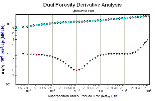
As in the case for the semi-log plot, the shape and location of this transition period or dual porosity signature are defined by the interporosity flow coefficient (λ) and the storativity ratio (ω) as shown in the plots below.
It is important to note that when analyzing dual porosity data that the value of apparent or total skin (s') should always be taken from the second semi-log straight line or the second radial flow region on the derivative plot.
Interporosity flow coefficient ( )
)
In a dual porosity reservoir, the interporosity flow coefficient is defined as the ratio of the permeability of the matrix (km) to that of the fractures (kf) defined as:

Note that the geometric coefficient (a) accounts for the shape of the matrix blocks. The interporosity flow coefficient is usually in the range of 10-4 to 10-8 and is always used in conjunction with the storativity ratio in dual porosity reservoirs.
Interporosity skin (sdp)
Interporosity skin is used in the transient interporosity flow dual porosity model. It is defined as the skin or pressure drop at the interface between the two porosities (matrix and fractures). If this skin is large, then this transient model becomes equivalent to the pseudo-steady state interporosity flow model.
Storativity ratio (w)
In a dual porosity reservoir, the storativity ratio is defined as the fraction of the total pore volume associated with one of the porosities. Specifically, in a naturally fractured reservoir it refers to the volume of reserves contained within the fractures and is defined as:

The storativity ratio has a significant effect on the short-term deliverability of a reservoir. It is usually in the range of 0.01 to 0.1 and is always used in conjunction with the interporosity flow coefficient in dual porosity reservoirs.
Types of interporosity flow
There are two types of interporosity flow that are used to model dual porosity systems: pseudo-steady state interporosity flow and transient interporosity flow.
Pseudo-steady state interporosity flow
This model is the most commonly used dual porosity model and assumes that the flow between matrix and fractures is in pseudo-steady state.
Transient interporosity flow
This model assumes that the flow between the matrix and fractures is transient, and that a positive skin (sdp ) exists at the interface between the two porosities. If this skin is large, then this transient model becomes equivalent to the pseudo-steady state interporosity flow model.
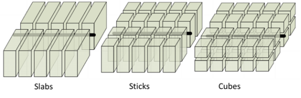
The three types of matrix geometry for model transient interporosity flow are slabs, sticks, and cubes.
A dual porosity system gives rise to two parallel straight lines on a semi-log plot. However, often the first line is obscured by early time effects such as wellbore storage. Moreover, if the interporosity flow is of the transient mode rather than the pseudo-steady state type, then in the transition between the two parallel semi-log lines, there exists a semi-log straight line of half of the slope of one of the parallel lines. In practice, these straight lines are difficult to observe uniquely.
Note: Calculations for various types of interporosity flow are summarized by Gringarten (1984).