Horizontal Multifrac Composite Model
Subtopics:
Plots, Forecast & Test Design, and Tables Tabs
With this model, you can specify an enhanced permeability in the region between fractures, and another permeability in the region beyond the tips of the fractures.
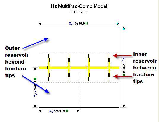
It is a rectangular model that contains an inactive horizontal well fed by multiple identical and equally-spaced transverse fractures. The portion of the reservoir between the fracture tips and the entire reservoir length is defined as the inner reservoir, and the rest is the outer reservoir, as illustrated in the figure below. The permeabilities of the inner and outer regions can differ, making this model useful for modeling a stimulated reservoir volume (SRV), created by hydraulic fracturing, which is fed by an unstimulated outer region.
This model calculates the reservoir's response from early-time storage and fracture flow, through the transition into boundary-dominated flow. The fundamental building block of this model is the tri-linear fracture model for a vertical well. The outer reservoir feeds the inner reservoir via linear flow, the inner reservoir feeds the fractures via linear flow, and the fluid within the fractures travels linearly towards the wellbore. However, for a horizontal well, the fluid within transverse vertical fractures actually has a radial flow pattern, and a convergence skin has been implemented in order to account for this. As a result, it is not possible to observe radial flow with this model.
| Note: | A detailed description of the model is given by Brown et al. (2009). |
The reservoir dimensions, number of fractures, and fracture half-length may be specified by the user, provided the entire wellbore and all fractures fit within the reservoir boundaries. The dimensionless fracture conductivity must also be specified. Dual-porosity behavior can be modeled within the inner-reservoir, but the outer-reservoir remains strictly homogeneous. A turbulence factor, D, can also be specified.
Parameters
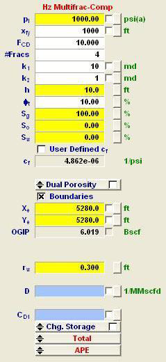
Pi = initial pressure
xfy = fracture half-length in the y-direction
FCD = dimensionless finite conductivity
#Fracs = the number of fractures that intersect the horizontal well.
k1 = permeability in the stimulated reservoir volume (between the fractures).
k2 = permeability beyond the fracture tips.
h = net pay
Φt = total porosity
Sg = gas saturation
So = oil saturation
Sw = water saturation
cf = formation compressibility
[Dual Porosity Parameters]
PSS = Transfer from secondary porosity to primary porosity is modeled as pseudo-steady state (PSS).
Transient Slabs = Transfer from secondary porosity to primary porosity is modeled as transient, using a slab shape factor.
Transient Cubes = Transfer from secondary porosity to primary porosity is modeled as transient, using a cube shape factor.
Transient Sticks = Transfer from secondary porosity to primary porosity is modeled as transient, using a stick shape factor.
ω = storativity ratio
λ = interporosity coefficient
sdΦ = interporosity skin (for transient dual-porosity only)
Xe = reservoir length
Ye = reservoir width
OGIP = original gas in place
Zw = z position of well within reservoir
Xw = x position of well within reservoir
Yw = y position of well within reservoir
rw = wellbore radius
CD1 = dimensionless wellbore storage (may be left blank)
CD2 = dimensionless wellbore storage 2
CpD = dimensionless storage pressure
D = turbulence factor (may be left blank)
AD = areal extent of reservoir
Eavg = average error
Itr = number of iterations
Plots, Forecast &Test Design, and Tables Tabs
Each model has three tabs: Plots, Forecast & Test Design, and Tables.

References
1. “Comparison of Fractured Horizontal-Well Performance in Conventional and Unconventional Reservoirs", E. Ozkan, SPE, Colorado School of Mines, M. Brown, SPE, Colorado School of Mines, R. Raghavan, SPE, Phillips Petroleum Co. (Retd.), and H. Kazemi, SPE, Colorado School of Mines. Paper SPE 121290, Presented at the 2009 SPE Western Regional Meeting held in San Jose, California, USA, 24-26 March 2009.
2. “Practical Solutions for Pressure Transient Responses of Fractured Horizontal Wells in Unconventional Reservoirs”, M. Brown, SPE, and E. Ozkan, SPE, Colorado School of Mines; R. Raghavan, SPE, Phillips Petroleum Co. (Retd.); and H. Kazemi, SPE, Colorado School of Mines. Paper SPE 125043, Presented at the 2009 SPE Annual Technical Conference and Exhibition held in New Orleans, Louisiana, USA, 4–7 October 2009.