Artificial Lift
Pumping
For pumping wells with recorded liquid levels, use the Pumping flow path. To select the Pumping flow path:
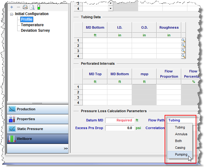
1. Open the Wellbore Editor, and select the Profile parameter set.
2. Click the Flow Path drop-down menu in the Pressure Loss Calculation Parameters section, and select Pumping. See Entering Wellbore Data for additional information.
The Pumping flow path makes the assumption that all liquids are pumped up the tubing (the wellbore requires a tubing string), that all gas is produced up the annulus, and that the pump is at the end of tubing (EOT). The Pumping flow path ignores tubing pressures; only entered or imported casing pressures are used to perform wellbore calculations. The final calculated sandface pressure is determined by breaking up the wellbore into individual sections.
A flowing row in the Production Editor is a row that contains production information (gas or liquid). A non-flowing (shut-in) row has a value of “0” or null (i.e., blank) for all volumes / rates.
With tubing landed below datum:
- The pressure drop is determined from the wellhead to the top of the liquid level using single-phase gas.
- Then, the hydrostatic pressure drop is determined from the top of the liquid level to the datum by multiplying the height of the liquid column by the liquid gradient.
With tubing landed above datum:
- The pressure drop is determined from the wellhead to the top of the liquid level using single-phase gas.
- The hydrostatic pressure drop is determined from the top of the liquid level to the end of tubing by multiplying the height of the liquid column by the liquid gradient.
- Finally, a multiphase flowing gradient is performed from the EOT to the datum.
The following columns are available in the Production Editor:
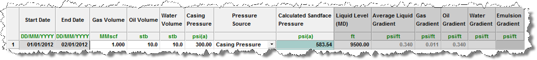
- Liquid Level (MD)
- Liquid Level (TVD)
- Gas Gradient
- Water Gradient
- Oil Gradient
- Emulsion Gradient
- Average Liquid Gradient
Harmony calculates and displays the average gradient for gas, oil, and water. Based on the water-oil ratio (WOR), it then calculates and displays an Emulsion Gradient (if applicable). Finally, Harmony divides the entire hydrostatic pressure drop of the liquid column by the column height to determine the average liquid gradient. Any and all gradients can be overwritten by the user, with the exception of the emulsion gradient, which is a calculated value.
Calculated sandface pressure for a flowing row:
In cases where oil and water rates are entered, Harmony assumes that when the well is flowing, only the lightest liquid (oil) is present in the static liquid column. Therefore, a water and emulsion gradient is not displayed, and the Average Liquid Gradient value is identical to the Oil Gradient.
Calculated sandface pressure for a shut-in row:
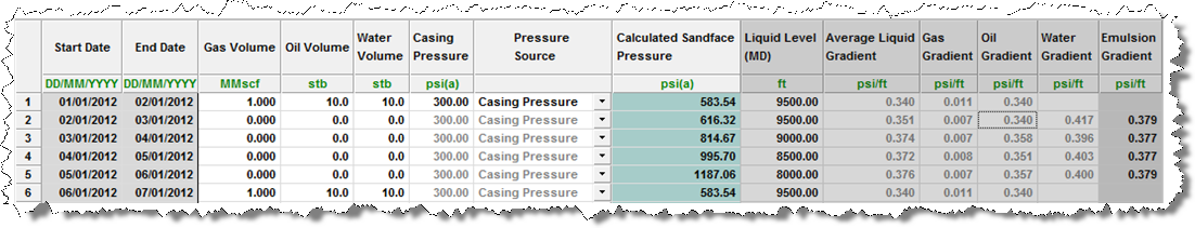
The first shut-in row sets the height of the static oil column. If the liquid level rises, the oil column also rises, followed by an emulsion. The WOR of the last producing row is used to calculate the emulsion gradient for all of the following shut-in rows in this period until the well begins to flow again.
Gas Lift
For wells on gas lift, select the Gas Lift flow path. To select the Gas Lift flow path:
1. Open the Wellbore Editor, and click Profile.
2. Click the Flow Path drop-down menu in the Pressure Loss Calculation Parameters section, and select Gas Lift. See Entering Wellbore Data for additional information.
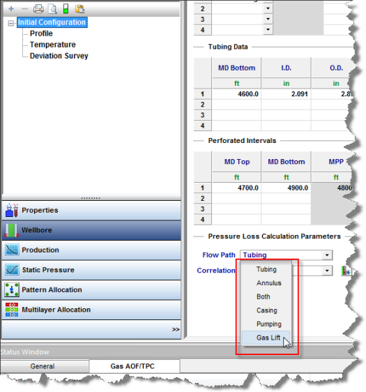
Additional options become available.
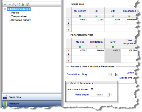
You can choose to model your Gas Lift system conventionally, with an operating valve and a packer, or as a “poor boy” system with no packer or valve.
Conventional Gas Lift
To model your Gas Lift system conventionally, click the Use Valve & Packer box. You must also specify the depth of the operating valve. If you do not specify a depth, Harmony will use a default valve location 10 feet above EOT. With a packer in place, you must use tubing pressure as your pressure source. Sandface pressures cannot be calculated using the casing side pressure source.
The wellbore calculations assume that none of the injected gas is lost to the reservoir(s), and that all of it is returned up the tubing. Sandface pressure calculations occur as follows:
- The pressure drop from the surface to the operating valve is determined using the sum of all production rates, plus the rate of gas injection.
- The pressure drop from the operating valve to the datum(s) is determined using production rates only.
"Poor Boy" Gas Lift
To model your Gas Lift system as “poor boy”, deselect the Use Valve & Packer box. Because there is no packer in place, it is possible to use either casing or tubing as your pressure source in order to perform sandface pressure calculations.
Just as in the conventional case, the wellbore calculations assume that none of the injected gas is lost to the reservoir(s). Note that pressure calculations differ depending on your pressure source (i.e., tubing or casing).
For tubing, the calculations occur as follows:
- The pressure drop from the surface to EOT is determined using the sum of the production rates, plus the rate of gas injection.
- The pressure drop from EOT to the datum(s) is determined using production rates only.
For casing side pressure, the calculations occur as follows:
- The pressure drop from the surface to EOT (or the most shallow layer above EOT, if applicable) is determined using only the gas injection rate.
- If there are layers above EOT, the pressure drop from the most shallow layer above EOT to EOT is determined using the gas injection rate, plus the rate of any fluids produced from the layer(s) above EOT.
- The pressure drop from EOT to the remaining datum(s) is determined using only the production rates from the layers below EOT.
Properties of Injected Gas
The properties of the injected gas may be different from the properties of the produced gas. You must enter your gas lift properties separately from produced gas properties in the Properties Editor.
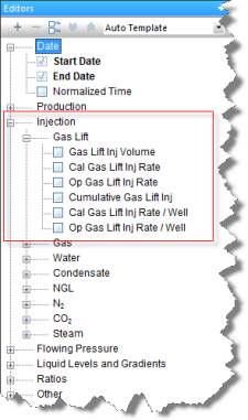
Note: In Harmony, gas lift injection is treated differently than gas injection. If you would like to model your well on gas lift, you must ensure that the injection rates (or volumes) are entered in the Production Editor in the Gas Lift Injection fields, not the Gas Injection fields.
Entering Rates into the Production Editor
Harmony supports three natural gas streams:
1. Under the Production node, click Gas. This is gas produced from the reservoir. If you have gas lift operations, this is a “net produced gas”; which is gas produced from the well minus the gas injected for gas lift.
2. Under the Injection node, click Gas Lift. This is the gas injected into the wellbore for gas lift injection purposes only.
3. Under the Injection node, click Gas Inj. This is gas injected into the reservoir for pressure maintenance, enhanced oil recovery (EOR), or disposal. This gas injection has nothing to do with gas lift.
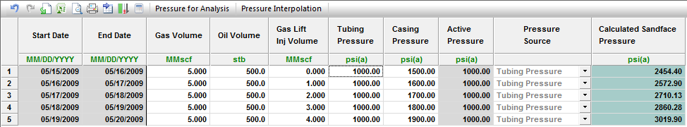
Therefore, in the following screenshot, the total gas received at the wellhead (gross produced gas) is the sum of Gas Volume and Gas Lift Inj Volume.