Flow Regimes
Subtopics:
Linear Flow within the Fractures (MFHW)
Vertical Radial Flow within the Fractures (MFHW)
Flow of fluid in the reservoir flows in different ways at different times. This is often a function of the shape and size of the reservoir. In this section, the basic flow regimes are categorized in terms of which time region they occur, and what kind of wellbore (vertical or horizontal) was used to drill into the formation.
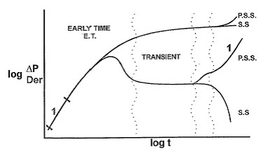
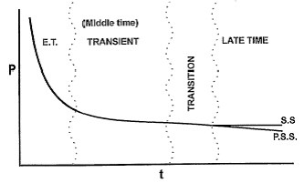
The following are typical derivative and pressure-time plots with the different time categories marked:
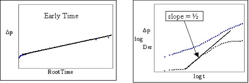
- Early Time (E.T.)
- Steady State (S.S.)
- Pseudo-steady State (P.S.S.)
Specific flow regimes that occur within each of the flow regime categories are listed below (for both vertical and horizontal wells):
| Wellbore Configuration | Early Time | Middle Time | Transition | Late Time |
|---|---|---|---|---|
|
Vertical Wells |
||||
|
Horizontal Wells |
||||
| Multi-fractured Horizontal Wells (MFHWs) |
|
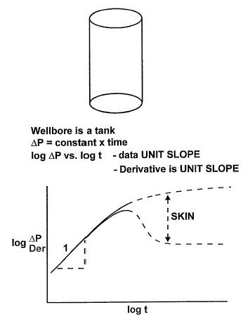
Afterflow / Wellbore Storage
When a producing well is shut-in at the surface, flow into the wellbore at sandface continues after shut-in. This type of flow regime is referred to as afterflow or wellbore storage, and can affect the analysis of the pressure data.
| Note: | Data affected by wellbore storage contains little or no information about the reservoir. |
Wellbore storage is typically controlled by the compressibility of the fluid in the wellbore. For a gas-filled wellbore, compressibility is high, and wellbore storage effects occur over a longer period of time. For a liquid-filled wellbore, compressibility is much lower, and wellbore storage effects dissipate more quickly. In some cases, typically in oil wells, both gas and liquid are present within the wellbore and the liquid level changes after shut-in. In these cases, wellbore storage is also affected by the changing liquid level, as well as compressibility.
Wellbore storage can be minimized by using a downhole shut-in. This operation reduces the wellbore volume and consequently the wellbore fills more quickly so you can see reservoir-dominated flow faster. This kind of operation is typically used to conduct a Closed Chamber Test (CCT) analysis to reduce the amount of time needed to gather data to see reservoir effects.
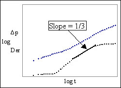
Bilinear Fracture Flow
Bilinear fracture flow occurs in hydraulically fractured wells when the conductivity of the fracture is finite. In this flow regime, two types of linear flow occur: one from the matrix to the fracture, and one from the fracture to the wellbore. This is usually evident in long fractures (which are hard to prop open effectively), or in natural fractures (which contain fracture-fill minerals).
Bilinear Flow – MFHW
In multi-fractured horizontal wells (MFHWs), when the conductivity of the fracture is finite, and the fracture length is greater than its height, bilinear flow can be observed. It occurs when two linear flows exist: one within the fracture (towards the well), and one within the formation (towards the fracture). This is identical to bilinear flow in a fractured vertical well.
Compound Linear Flow – MFHW
After the fractures have interfered with each other, compound linear flow may be observed. It is defined by flow from an outer zone towards the region stimulated by the fractures. This can be observed in fields where well spacing is sparse. However, with close well spacing, it is not observed before interference from adjacent producing wells occurs.
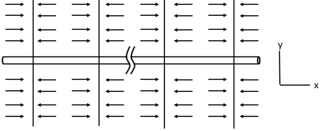
Early Linear Flow – MFHW
Identical to linear flow in a hydraulically fractured vertical well, this flow regime occurs when there is linear flow towards the fractures of a multi-fractured horizontal well (MFHW) and the transients within the fractures have stabilized.
This linear flow regime is expected to be the dominant flow regime, as demonstrated from production analysis results (Nobakht, 2011).
Early Radial Flow – MFHW
This flow regime, depicted below, was initially proposed when hydraulic fracturing was first attempted on horizontal wells in the mid 1990s. It would be observed after the end of the Early Linear Flow, but before the fractures start interfering with each other. It is only seen if the fractures are far apart or very short (e.g., acid fracs), and is not likely to be observed with the close fracture spacing of today’s unconventional wells (Liang et al 2012).
Elliptical Flow
Elliptical Flow occurs when fluid has started to flow from the reservoir at either end of the horizontal wellbore. It is a transition between linear horizontal flow and horizontal radial flow.
Horizontal Radial Flow
Horizontal radial flow can be observed during the middle time region, after the radius of investigation (rinv) has expanded well beyond the length of the wellbore.
Late Radial Flow – MFHW
This flow regime defines radial flow around the multi-fractured horizontal well (MFHW) after compound linear flow. It is characterized as a zero slope on the log-log derivative plot. This flow regime is only observed if the well exists all alone, in an undeveloped field, and would require an extremely long time and area to develop in tight unconventional formations. As such, it is unlikely to be observed in practice.
Late Time Region
The late time region begins when the radius of investigation (rinv) has reached all of the boundaries. During this time period, stabilized flow has been reached, and the reservoir exhibits pseudo-steady state or steady state flow.
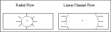
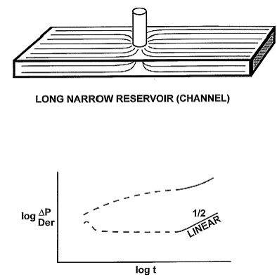
Linear Channel Flow
Linear channel flow only occurs in long, narrow reservoirs. Initially the radius of investigation (rinv) hasn’t reached the reservoir boundaries and radial flow is observed. After the two parallel boundaries have been reached, a period of linear channel flow can be observed.
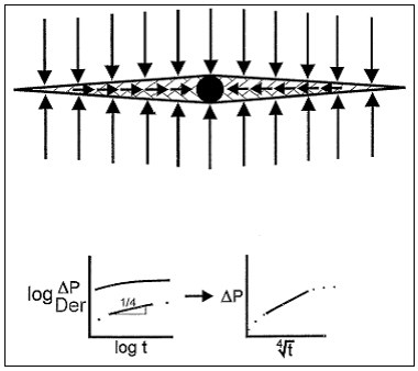
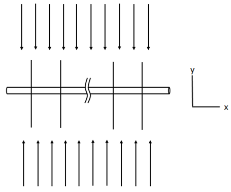
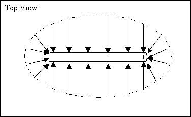
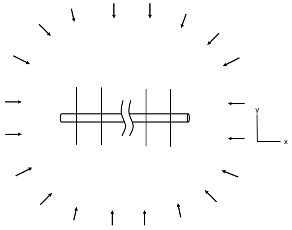
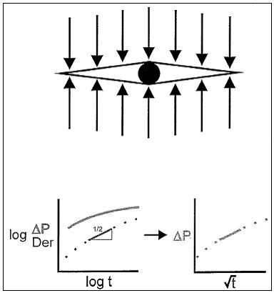
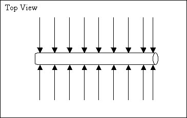
Linear Flow within the Fractures – MFHW
For biwing planar fractures (where the fracture length is much greater than the fracture height), linear flow can develop after vertical radial flow within the fractures in multi-fractured horizontal wells (MFHW).
| Note: | Linear flow within the fractures is not normally observed in data because it is masked by wellbore storage. |
Linear Fracture Flow
Linear fracture flow occurs in hydraulically fractured wells when the conductivity of the fracture is infinite. In this situation, the permeability of the fracture is so high that the pressure throughout the fracture is constant.
Linear Horizontal Flow
After the radius of investigation (rinv) has reached the top and bottom of the formation, fluid travels from the formation perpendicular to the length of the wellbore. This is referred to as intermediate linear or horizontal flow.
Pseudo-Steady State Flow
Pseudo-steady state (PSS) flow occurs during the late time region when the outer boundaries of the reservoir are all no-flow boundaries. This includes not only the case when the reservoir boundaries are sealing faults, but also when nearby producing wells cause no-flow boundaries to arise. During the PSS flow regime, the reservoir behaves as a tank. The pressure throughout the reservoir decreases at the same, constant rate.
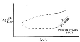
| Note: | PSS flow does not occur during buildup or falloff tests. |
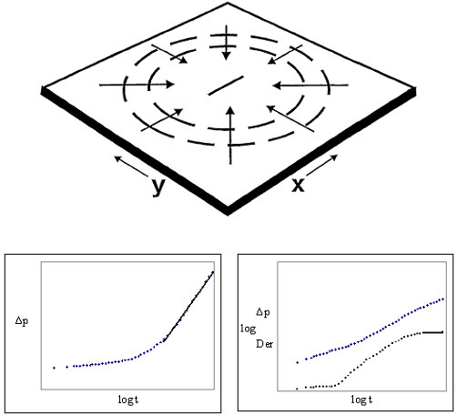
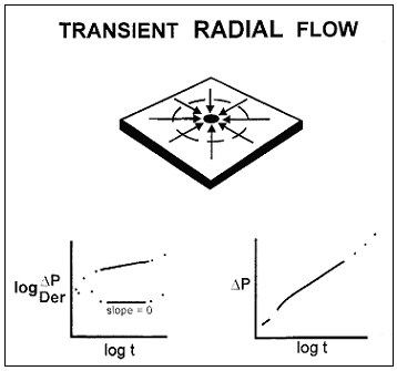
Radial Flow
In this flow regime, flow is in the horizontal radial direction. This type of flow exists in the time period before the pressure transient has reached the boundaries of the reservoir (infinite-acting time period).
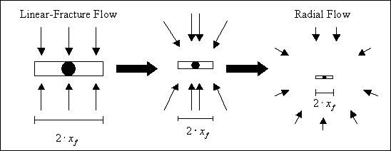
Radial flow is often observed following other flow regimes. The emergence of radial flow in an infinite conductivity hydraulically fractured well is shown below. When the radius of investigation (rinv) is small, linear fracture flow is observed, and as it expands, the flow increasingly becomes radial.
Single No-Flow Boundary
Single no-flow boundary flow occurs during the transition region when a well is located near a single no-flow boundary. A no-flow boundary can be a physical entity, such as a sealing fault, or can occur when two producing (or two injecting) wells are adjacent to one another.
Mathematically, a situation in which a well is next to a sealing fault can be modeled by removing the fault, and placing an image well with a flow rate equivalent to the producing well as shown in the diagram below.
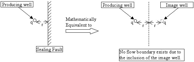
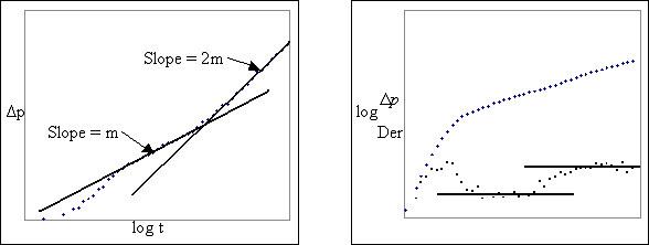
As shown on the plots below, the pressure response on a semi-log or derivative plot shows a doubling of slope when a single no-flow boundary is present.
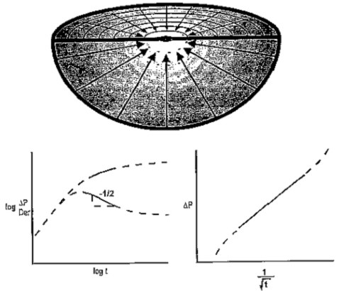
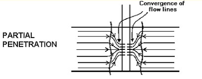
Spherical Flow
Spherical flow occurs when a vertical well is partially penetrated or during RFT/MDT/WFT tests. Spherical flow is the occurrence of radial flow in both the horizontal and vertical directions.
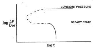
Steady State Flow
Steady state flow occurs during the late time region when a constant pressure boundary exists. Constant pressure boundaries arise when the reservoir has aquifer support, or gas cap expansion support.
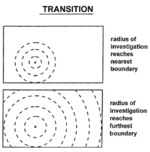
Transition Region
The transition region or period occurs between the time the radius of investigation (rinv) reaches the closest boundary, and the time it reaches the furthest boundary.
Vertical Radial Flow
Vertical radial flow occurs only in horizontal wells. In represents the early time region before the radius of investigation (rinv) has reached the top or bottom of the formation. Vertical radial flow into a horizontal wellbore is similar to radial flow in a vertical wellbore, except that it is in the vertical direction.
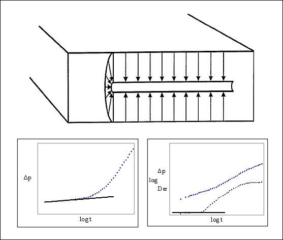
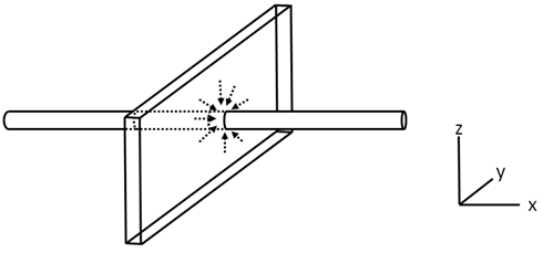
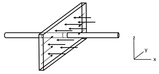
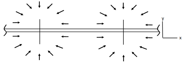
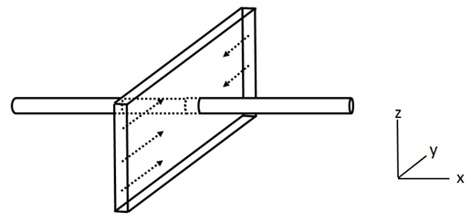
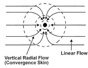
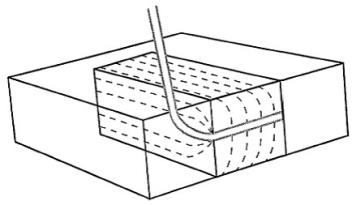
Vertical Radial Flow within the Fractures – MFHW
In horizontal wells that have not been stimulated with hydraulic fractures, a radial flow period develops in the vertical plane, and is defined as vertical radial flow. When a horizontal wellbore intersects one or more planar fractures, which is the conceptual model adopted for a multi-fractured horizontal well (MFHW), fluid flows through the fractures into the wellbore. This flow pattern eliminates the possibility of observing vertical radial flow between the planar fractures, but introduces the possibility for developing vertical radial flow within the fractures themselves, as shown below.
| Note: | This flow regime is not observed in data because it is masked by wellbore storage. |